Applet
Instruct the students to go to http://lushprojects.com/circuitjs/ Alternatively, if the link does not work, go to
http://www.falstad.com/circuit/
- Choose circuits, then basic, then Ohm's Law.
- Ohm's Law: V = I * R. The voltage going into each branch is the same. Which branch has more resistance?
- Thus, which one has more current? (Answer: The branch with less resistance.)
Virtual models such as this have many benefits: they save time, money/resources, and are easily applicable to real-life scenarios. By planning out our circuit through online software, we reduce the chances of making a mistake - if an electrical engineer makes a mistake in a very complicated circuit, he or she may have wasted days' worth of work. If he or she had planned out the circuit through modeling software, the mistake could have been avoided.
Applet Exercise: The Timer Circuit
Before we start working with our physical 555 timer chip, let’s go back to the circuit simulator and click the following.Circuits>555 Timer>Square Wave Generator.
When the 555 timer circuit appears, note that the pin numbers along side the IC chip are not listed in sequence. This is done to make the schematic (circuit diagram) much easier to follow. Oftentimes, pin 1. Called GND, or ground, is shown as being connected to a ground symbol, drawn using three progressively shorter horizontal parallel lines with a vertical line attaching midway of the longest (top) horizontal line. (the instructor can illustrate what the symbol looks like.) Several other connections throughout the circuit may connect to a GND, or ground, symbol. In reality, all of these connections are connected together at the same node, usually the – (negative) rail or negative terminal of the battery. This convention helps to maintain clarity in the schematic diagram by reducing the number of wires needed to represent the circuit. Note that there is no LED pictured in the schematic diagram. We will connect our resistor and LED to pin 3 (output) of the 555 timer chip as we build the circuit.
Make the following changes in the component values in the circuit:
- Change battery voltage to 9 volts DC
- Change resistor values to 10KOhms
- Change capacitor value to 10uf
- Select and connect the positive end of an LED to pin 3 of the 555 timer chip
- Connect the negative lead of the same LED to one lead of a 10KOhm resistor (You may have to add a wire to make this connection)
- Connect the other end of the same 10KOhm resistor to GND
- Reset the circuit by clicking Reset
- Run the simulator and check that the circuit operates
- The LED should blink
- Stop the simulator
Student Exercise:
Changing the blink rate of the LED
What effect will increasing the capacitance have on the blinking rate of the LED? Allow students to answer. (LED will blink slower.)
Ask student s to edit the value of the 10uf capacitor and increase it to 100uf.
Reset and Start the simulator.
What happened to the blinking rate of the LED? (Answer: slower)
Let's make a circuit based off one of the designs.
- Choose Circuits → 555 Timer Chip → Square
- Wave Generator
- Build the circuit shown using the diagram below and the circuit applet.
- Use the output to power the LED Circuit from first exercise
- “555 Timer Circuit” in your handout gives the circuit, for convenience
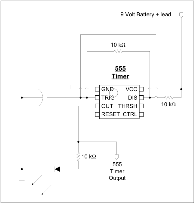
- Follow the rough layout shown here on your bread-board. It can also be found in the student's packets
- Use the black wire and left rails for ground.
- Use the red wire and right rails for the 9V battery + lead
For detailed instructions on how to complete this circuit, click here: Link. A printable copy can be found here: Download
Help the students get a working model. To orient the 555 chip, make sure the notch in the chip is facing upwards. If facing the opposite direction, the chip will not work.
|
If this is the half day (or middle school) workshop, Go to Summary |
|
If this is the full day (or high school) workshop, Continue to page 6 |