More Terminology
Analog Circuits - What we've seen up to now. It can have any voltage (in our case, between 0V and 9V). It's a useful interface for the "real world."
Digital Circuits - It has only two voltages (0V and 5V). It is very useful in processing information reliably. These circuits use logic gates, which will be explored below, and send pulses of current in the form of 0s and 1s to make decisions.
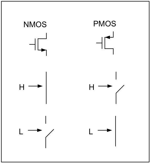 Transistors - Basically a switch. There are two types that we will look at:
- NMOS – closed when input is high
- PMOS – closed when input is low
- Go to http://lushprojects.com/circuitjs/
- Choose Circuits → Logic Families → CMOS → CMOS Inverter
- Click to toggle input. What happens to the output?
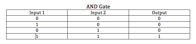
Logic Gates - Can be used to build up complex functions. For the programming-savvy, logic gates are essentially the "And" and "Or" functions. Instructors, create charts on a whiteboard or other empty space. The charts should look like the image below, but with none of the data filled in. After they make the basic circuit below, ask them for results to fill in the chart.
- Reload http://lushprojects.com/circuitjs/
- Choose Circuits → Blank Circuit
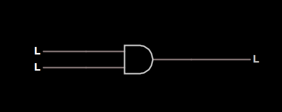
- Choose Draw → Logic Gates Input and Output → Add AND Gate. Alternately, hit "2" on your keyboard. Drag the cursor aross the screen to add this element.
- Choose Draw → Logic Gates Input and Output → Add Logic Input. Alternately, hit "i" on your keyboard. Drag two of these inputs form the left side of the AND Gate.
- Choose Draw → Logic Gates Input and Output → Add Logic Output. Alternately, hit "o" on your keyboard. Drag one output from the right side of the AND Gate. Look at the picture on the right for reference.
- Click to toggle inputs (The Hs and Ls on the left side). What happens to the output? When recording results in the chart, treat "L" in the input or output as a 0, and treat "H" in the input or output as a one.
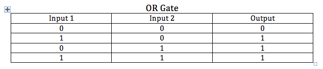
Now, we will focus on OR gates rather than AND gates.
- Reload http://lushprojects.com/circuitjs/
- Choose Circuits → Blank Circuit
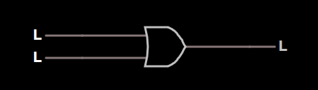
- Choose Draw → Logic Gates Input and Output → Add OR Gate. Alternately, hit "3" on your keyboard. Drag the cursor aross the screen to add this element.
- Choose Draw → Logic Gates Input and Output → Add Logic Input. Alternately, hit "i" on your keyboard. Drag two of these inputs form the left side of the AND Gate.
- Choose Draw → Logic Gates Input and Output → Add Logic Output. Alternately, hit "o" on your keyboard. Drag one output from the right side of the AND Gate. Look at the picture on the right for reference.
- Click to toggle inputs (The Hs and Ls on the left side). What happens to the output? When recording results in the chart, treat "L" in the input or output as a 0, and treat "H" in the input or output as a one.
Flip-Flops - Used to implement “memory” in a circuit. Essentially, it allows circuit behavior to change over time.
- Reload http://lushprojects.com/circuitjs/
- Choose Circuits → Sequential Logic → Flip-Flops → Master-Slave Flip-Flop
- Click to toggle the input under “D”. When does the output under “Q” change?
| On to page 7! |