Before building our first circuit, it is a good idea to model the circuit on the computer using a circuit simulator applet. It can be found here: first circuit simulation
After you have modeled the circuit on the computer, use the breadboard, one resistor, one battery, and one LED to build the circuit. Follow the "LED Circuit" in your handout. It can be found here: hand-out for middle school students or hand-out for high school students
Note: Ask the students what would happen if both leads of the battery snap were connected while plugged into the battery. DON'T DO IT. The battery may overheat or even explode. This is known as a "short circuit," and can happen inside a circuit as well.
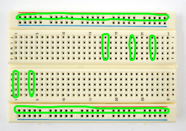 The breadboard is used to make quick, solderless connections between components. Connections are made by inserting the wire or component lead into the appropriate location. If you view the board with the center divider space running horizontally, then
5 holes in each column above the mid section of the board are connected by the internal wiring of the board. So, if one lead of a resistor is inserted into a hole in a particular column, and a wire is inserted into another hole in the same column,
the resistor lead and the wire will be connected. The entire column of 5 holes is called a node, or connection point. The columns located below the mid section of the board work the same way. Each column of 5 holes is independent of the next column
beside it. The double rows of holes located along the top and bottom edges of the board are connected in the same way, but in row format instead of by column and can be used as voltage connection nodes, sometimes called rails.
The breadboard is used to make quick, solderless connections between components. Connections are made by inserting the wire or component lead into the appropriate location. If you view the board with the center divider space running horizontally, then
5 holes in each column above the mid section of the board are connected by the internal wiring of the board. So, if one lead of a resistor is inserted into a hole in a particular column, and a wire is inserted into another hole in the same column,
the resistor lead and the wire will be connected. The entire column of 5 holes is called a node, or connection point. The columns located below the mid section of the board work the same way. Each column of 5 holes is independent of the next column
beside it. The double rows of holes located along the top and bottom edges of the board are connected in the same way, but in row format instead of by column and can be used as voltage connection nodes, sometimes called rails.
LED Circuit Prototyping Exercise
- Let's build the LED circuit and see it working.
- Bend both leads of a 10 K ohm Resistor at right angles and plug the resistor into the breadboard. Leads must be on different nodes.
- Bend the long lead (+) lead of the led outward and then downward to make a small knee in the long lead. This will effectively make both leads plug much easier into the breadboard.
- Plug the long lead of the LED to the same node as one end of the 10 K Ohm resistor.
- Connect a red wire from one of the outer rails to the other end of the 10 K Ohm resistor. Let us call this rail the Positive + rail.
- Connect a black wire from a different rail to the free end (-) end of the LED. This rail is the Negative, or Ground rail.
- Connect the red wire from the battery snap to the Positive rail where the red wire is connected.
- Connect the black wire of the battery snap to the Negative rail where the black wire is connected.
- Connect the 9 volt battery to the battery snap and check that the LED illuminates. You are making progress!
- Optional Question: How long will this LED remain lit? Energizer Alkaline batteries claim a lifetime of 625 mAh, which is equal to 2250 C. How long will it take to use up 2250 C of charge? (Answer: (9V/1000Ohms) = 9 mA, 2250/9 mA = 250,000 s = 4166 min = 69 hours = 2.9 days.)
- Disconnect the battery.
- Optional: Try adding two LEDs
| On to page 5! |