One of the key considerations in choice of a computing platform and a software tool is the size of the problem and the number of calculations needed to be done. The problem described in this case study is, as you might suspect, requires little in the way of computing power and software, so we choose the least restrictive/least expensive environment we can find. Since we're dealing here with a system of three ordinary first-order differentials (ODEs), with a system dynamics approach, I would choose to use a system dynamics modeler known as STELLA from High Performance Systems. STELLA runs on both Macintosh and PC Windows computer, and is designed to handle systems of differential equations with the Euler's and Runge-Kutta numerical methods as a part of the software. The interface is graphical -- to build a model a researcher selects an appropriate icon to represent the various mathematical components of the system. The software allows for simple creation of run-time graphs and data tables, both of which can be exported to other packages, including high-end visualization packages. The Chesapeake Bay Labs in Solomons Island MD have recently created a translator for STELLA that allows one to do spatial modeling with STELLA, with the generation of code in the C programming language that can be run on parallel architectures.
Sample Solution to the Case Study
One strategy for this model, even though it is relatively simple, is to break the model down into three "submodels", then create the connections between the various components. In this model, we are looking at three species -- NO, NO2, and CO, basically the interaction of CO with the NOx system. For this model development, the individual parts of the algorithm (the last graphic under the Algorithms section) were used as the "guide" for building this particular model. Each of the three parts has essentially the same layout:
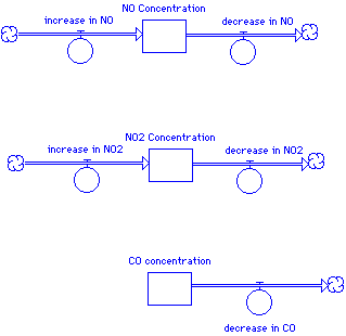
In this beginning model layout, we use stocks to represent an accumulation of NO, NO2, and CO over the simulation time. At the beginning of the simulation, each stock will contain some initial amount of chemical (or have a zero initial concentration). The flows represent the rate of change -- a flow pointed in represents, common sensically, an increase in the concentration while a flow out represents a flow out. Notice that the two nitrogen oxides are both being produced and being consumed, while in this simple model CO only decreases over time.
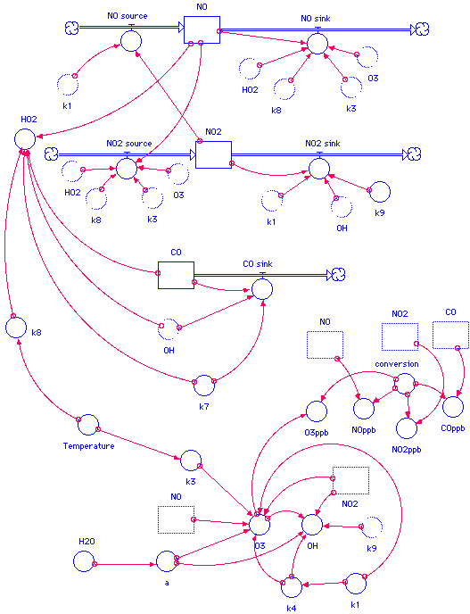
In the next step, each of the submodels is fleshed out to include those components that has some influence over the flows, which in turn modify the values in the stocks. For the NO subsystem, for example, the algorithm suggests that the rate constants k1 influences the rate of NO increasing, while the rate constants k3 and k8, as well as the concentrations of HO2 and O3, influence the removal of NO. The algorithm also suggests that the ever-changing concentration of NO2 is involved in the increase of NO, but we'll make this connection in a minute. and O3, influence the removal of NO. The algorithm also suggests that the ever-changing concentration of NO2 is involved in the increase of NO, but we'll make this connection in a minute.
Each submodel is fleshed out in a similar manner. The connector arrows in STELLA indicate that the variable from whence the connector begins provides input to the icon at the pointy end of the connector (pointy - how's THAT for technical jargon!). Notice in the NO subsystem that the concentration of NO itself plays a role in the algorithm for the removal of NO, hence there is a connector from the stock to the "decreasing NO" flow.
Once the individual subsystems are built, we can connect each of the submodels as the algorithm suggests. We also at this point explicitly include, at the bottom of the model, a variety of "static" calculations that need to be made, such as the calculation for a, O3, and some of the other species indicated in the algorithms graphic. In order for the graphical interface to be designed in an uncluttered manner as possible, we can make "ghost" copies of some of the icons -- for example, we need the three stocks as inputs for some of the calculations -- we can copy the icons and put them closer to their dependent variables so that we don't have too many connectors overlapping each other:
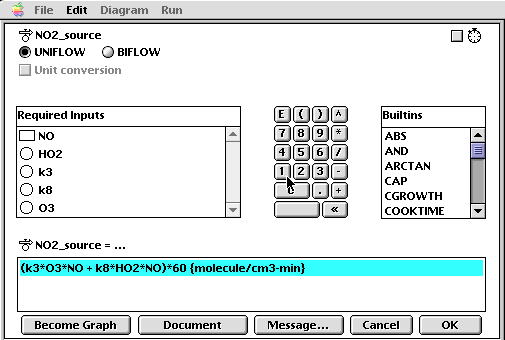
Once the model has been built, each of the icons must be "coded" with the appropriate algorithm, constant, or initial value. For example, the flow for NO2 input is coded with the graphical interface as follows:
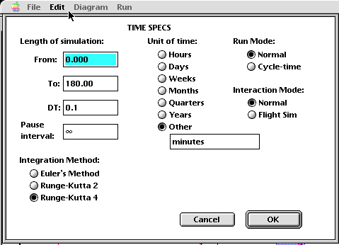
Once each of the stocks, flows, and converters have been provided with the appropriate algorithms or values, the model is in a runnable condition. The last step, at least for this particular modeling tool, is to choose a simulation time and which numerical method (from a library of three!) with which to do the algorithm analysis. In this particular example, a run time of 180 minutes was chosen, with a time step (dt) of 0.1, meaning that the system is re-evaluated every six seconds! Due to the relative complexity of this model, the Runge-Kutta 4 method was chosen. Each of the three algorithms work, but with tradeoffs! Use of Euler's Method, for example, will compute ballpark answers, but in a fashion that is not computationally expensive. If you look at the algorithm for Euler's Method, you should notice the simplicity of the recipe, compared with the increasing complexity of the Runge-Kutta techniques. As a model-builder and certainly as a model user, the user needs to make tradeoffs between performance of the model and the amount of time it takes to produce an answer. A 48-hour weather model that takes 80 hours to produce an answer is not of much use! If you couple the need for a relatively accurate answer in a reasonable amount of time with the expense of using higher-performance computing platforms (a Cray charges about $250/CPU hour), you should understand the need to balance performance and computational expense.
A typical strategy is to choose a large step size and a simple numerical method for the first several runs, looking to see if the output is "reasonable" -- is the model, for example, producing values that physically don't make sense or are out of scale? If the model is generating ballpark solutions, then the modeler can decrease the step size and/or increase the complexity of the numerical method. At this stage the model is ready for "production runs", in which the user can manipulate the initial values and conditions to generate solutions for parameters of his or her interest.
This particular software also generates mathematical equations for those of you (us) who take comfort in those kinds of things:
CO_concentration(t) = CO_concentration(t - dt) + (- decrease_in_CO) * dt
INIT CO_concentration = (50) {initial concentration in ppb}/4.08E-11 {molecule/cm3}

OUTFLOWS:
decrease_in_CO = (k7*CO_concentration*OH)*60 {molecule/cm3-min}
NO2_Concentration(t) = NO2_Concentration(t - dt) + (increase_in_NO2 - decrease_in_NO2) * dt
INIT NO2_Concentration = (10) {initial concentration in ppb}/4.08E-11 {molecule/cm3}

INFLOWS:
increase_in_NO2 = (k3*O3*NO_concentration + k8*HO2*NO_concentration)*60 {molecule/cm3-min}
OUTFLOWS:
decrease_in_NO2 = (k1*NO2_Concentration + k9*OH*NO2_Concentration)*60 {molecule/cm3-min}
NO_concentration(t) = NO_concentration(t - dt) + (increase_in_NO - decrease_in_NO) * dt
INIT NO_concentration = (10) {initial concentration in ppb}/4.08E-11 {molecule/cm3}

INFLOWS:
increase_in_NO = k1*NO2_Concentration*60 {molecule/cm3-min}
OUTFLOWS:
decrease_in_NO = (k8*HO2*NO_concentration + k3*O3*NO_concentration)*60 {molecule/cm3-min}
a = 1/(1+((2.9E-11*0.2E20)/(2.2E-10*H2O)))
conversion = 4.08E-11 {molecule/cm3 to ppb}
COppb = conversion*CO_concentration {ppb}
H2O = 0.3E18
HO2 = (k7*CO_concentration*OH)/(k8*NO_concentration) {molecule/cm3}
k1 = 0.0089 {1/s}
k3 = 2.2E-12*exp(-1430/Temperature) {cm3/molecule-s}
k4 = 0.0028*k1 {cm3/molecule-s}
k7 = 2.2E-13 {cm3/molecule-s}
k8 = 3.7E-12*exp(240/Temperature) {cm3/molecule-s}
k9 = 1.1E-11 {cm3/molecule-s}
NO2ppb = conversion*NO2_Concentration {ppb}
NOppb = conversion*NO_concentration {ppb}
O3 = k1*NO2_Concentration/(k3*NO_concentration+a*k4)
O3ppb = conversion*O3
OH = 2*a*k4*O3/(k9*NO2_Concentration) {molecule/cm3}
Temperature = 298 {K}
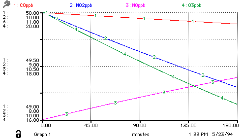
Again, once the model has been generated, a variety of sample runs can be conducted -- a movement from being a model-builder to being a model-user/analyst:
You might wish to consider building this particular model, using an architecture of your choice. If you have access to a Macintosh, there is a freeware pseudo-STELLA software package Madonna available via ftp.
You can also choose to run the interactive model available on Shodor's workstation. Use the form provided to send your input data to the workstation.
|
