We have just completed our experimentation with a triangle. Now, let us move on to different shapes such as rectangles. To do this, we first have to build our bridge. Remove the top node, then add two more directly above your fixed node and your horizontal rolling node. Go ahead and add your members, forming the perimeter of your rectangle.
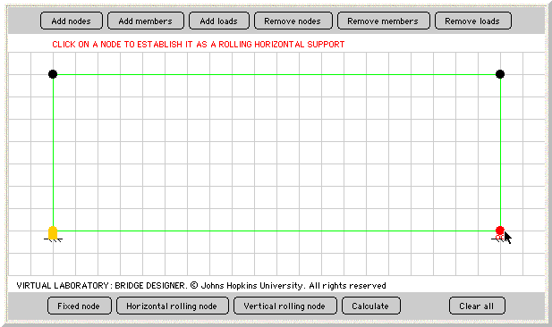
You will see that, as you add and remove different components of your bridge, the fixed node and horizontal rolling node will disappear. You will ned to add them back in their original positions (lowers left and right).
Before you add the loads and calculate, think about what might happen to this bridge. Is it strong enough to stand up? Will it topple? Also think about why this might happen.
Now, add two 50-pound loads to each upper node on the bridge. This way, we are distributing the weight equally throughout our bridge.
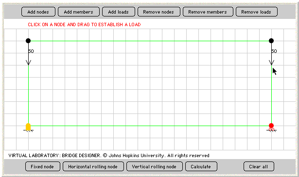
Calculate the forces in our bridge. What happened? It would seem that we failed, but what exactly does this error mean?

To figure out what this means, imagine a rectangle made out of straws. Each corner of the structure is fastened with only a single pin.
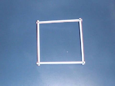
This is a physical model of our computational model. It also helps some people more easily understand what the computer is doing for us. What type of problems could be associated with this square when weight is placed on top of it? Let's take a look at the picture below.
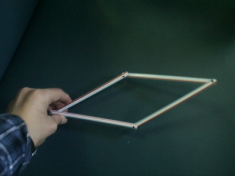
According to this demonstration, the square model does not have the support needed to be able to stand when a downward force is applied. It is very unstable, and moves around very easily.
How can we change this model so that it will stand on its own, and have the supports to stay standing when a load is added to it? There are only two ways to connect the nodes without overlapping members...diagonally! So, let's go ahead and do that. Add a member from the upper-left node to the lower-right node. Then, go ahead and calculate your forces.
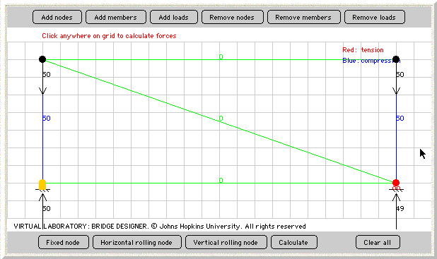
The question as to what happened is a little bit easier to understand this time. As you can tell, nothing happened to the middle three members. But, why is that? Because the loads are exactly the same direction as the members, the force of the load is going to be the same as the force of the members. The middle members are not going to be affected because they stay in the same position, having no other role except holding the vertical members together.
We're still trying to get a rectangular shape that will get different amounts of tension and compression on different members. We've so far gotten a) a structure that collapses and b) a structure where there are no changes. What else can we try without adding any more nodes?
Most people suggest placing another member, this one extending from the top-right node to the bottom-left node, in addition to the other diagonal member. What happens when you calculate these forces? ANOTHER ERROR? But, why?

We get a message from the Applet that says Members +3 must equal twice the Nodes. We can simplify that to M + 3 = 2 * N, where M is the number of members and N is the number of nodes. Click here if you need help solving this equation.
This equation gives the number of members needed to hold up the bridge. There cannot be too many (as in this case), or too few, where the bridge will collapse.
| On to Challenges! |