In Straws We Trussed - Page 6
EXPERIMENTING WITH DIFFERENT SHAPES
We have just completed our experimentation with a triangle truss. Now, let us move on to different shape - a rectangle. To do this, we first have to build our bridge. Remove the top node, then add two more directly above your fixed node and your horizontal rolling node. Go ahead and add your members, forming a rectangle.
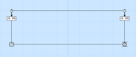
You will see that as you add and remove different components of your bridge, the fixed node and horizontal rolling node will disappear. You will need to add them back in their original positions (lower left and right).
Now, add two 50-pound loads to each upper node on the bridge. This is the same as the 100-pound load on the triangle truss, but distributed (divided into equal parts, in this case two) among the free nodes of the bridge.
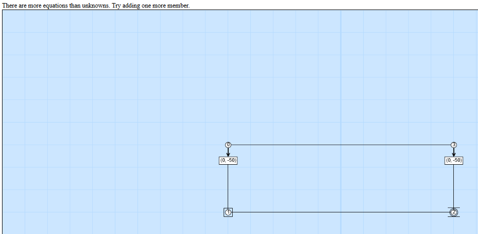

Calculate the forces in our bridge. What happened? It would seem that we failed, but what exactly does this error mean?
To figure out what this means, imagine a rectangle made out of straws. Each corner of the structure is fastened with only a single pin. The 'single pin' is important - for truss structures it is assumed that the node connections are very simple and don't resist weight themselves, i.e. that they can be represented with a single connecting pin.
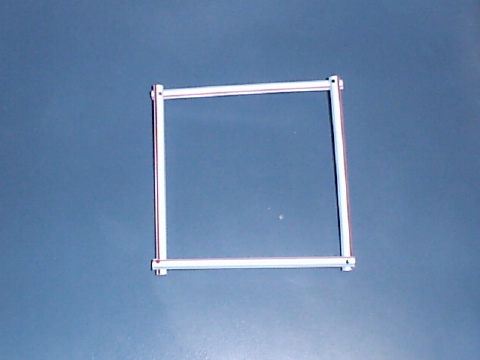
This is a physical model of our computational model. It helps some people more easily understand what the computer is doing for us. How well does this rectangle resist loading? With the physical model we can actually test!
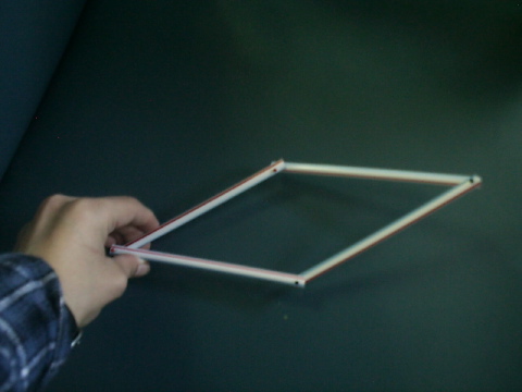
If we are very careful, we can probably squeeze our rectangle by pushing down on the corners, however, as shown in the picture above, the rectangle can very easily change into the shape of a parallelogram if we don't apply the forces perfectly! When the structure moves like this it is no longer able to resist the loads, and we say that the truss is unstable. The message the computer gives us tells us that there is 'no solution', meaning that it is unable to figure out what the tension and compression in the structure is, because that depends on the shape of the structure and the structure can change into all sorts of different shapes! To build a stable structure, we will have to avoid using rectangles and stick with triangles.
How can we change this model so that it will stand on its own, and have the supports to stay standing when a load is added to it? There are two ways to connect the nodes without overlapping members...diagonally! Add a member from the upper-left node to the lower-right node. Then, go ahead and calculate your forces.
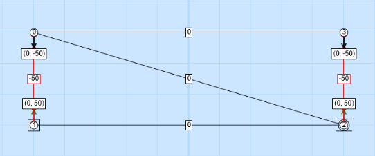
What happens this time? In this case, the middle three all have calculated loads of zero, meaning neither tension or compression, but why is that? Because the loads on the corners are applied in exactly the same direction as the vertical supporting members, these members are in the position to support all of the load! The middle members are actually not necessary to support the load, as long as it's perfectly vertical, however they are still important - they help make sure that the nodes cannot move side-to-side and thus make sure that the truss is stable.
The rectangular shape doesn't really behave as expected - so far we've gotten a) a structure that collapses and b) a structure where some members carry all the load and others carry nothing. Can we distribute the load more evenly?
Let's try by placing another member, this one extending from the top-right node to the bottom-left node, in addition to the other diagonal member. What happens when you calculate these forces? ANOTHER ERROR? But why?

We get a message from the Applet that says "Members + 3 must equal twice the Nodes". We can simplify that to M + 3 = 2 * N, where M is the number of members and N is the number of nodes. In this example we have 4 nodes, so how many members are necessary? Click here if you need help solving this equation.
Think for a moment about our first triangle example. In that case we had three nodes and three members, so 'members plus 3' (6) was indeed equal to 'twice the number of nodes' (also 6).
This equation gives the number of members needed for a truss. There cannot be too many (as in this case), or too few (like the case where the rectangle was unstable). As Goldilocks would say, It has to be 'just right'.
Now that we've learned how to construct trusses using the truss applet, let's challenge ourselves to build a truss with optimal numbers for internal tension and compression.
| On to the Computational Challenge! |