This last activity will be quite time-intensive. Now that we've learned a lot about electrical engineering, we can design our own advanced circuits. The goal is to create an array of lights that blink at different time intervals - it would be a type of basic clock. It will involve many of the components talked about in the previous pages - resistors, counters, capacitors, diodes, etc. A diagram of the circuit is below. Clicking on it will open a new tab with an enlarged version.
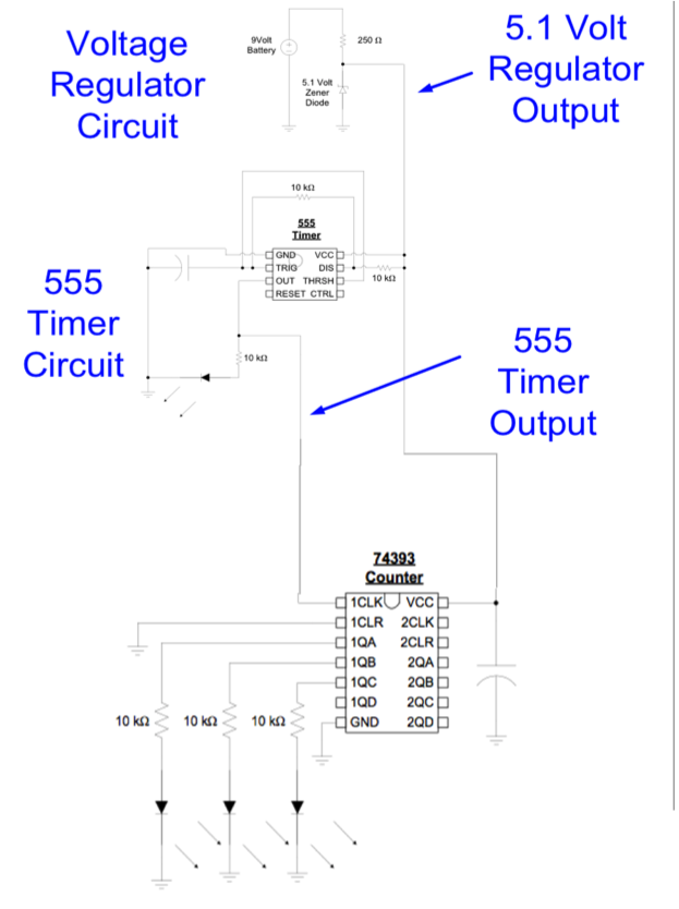
However, most digital chips work on 5V or less - the battery we are using is 9V. As a result, we need to "regulate" the voltage from 9V to 5V. To do this, we must add a diode.
- Be sure that the battery is disconnected from the circuit.
- Find an unused location on the breadboard and plug in the Zener diode. Be sure to position the positive lead near a GND location. Connect a black wire from GND to the positive lead of the Zener diode (Remember that the Zener diode is connected in reverse!)
- Connect the 249 ohm resistor to the negative lead of the Zener diode.
- Connect the other lead of the resistor to the 9 volt battery or to the 9 Volt Positive rail using a red wire.
- Connect a wire of a different color from the junction (node) of the resistor and Zener diode to an unused rail on the breadboard. This will become our new 5.1 volt supply location.
- Now, remove the red wire connecting 9 volts to Vcc (pin 8) of the 555 timer and connect the wire to the new 5.1 Volt supply rail. The other end of the red wire should still be connected to Vcc (pin 8) of the 555 timer IC.
- If there are other red wires connected to the 9 volt rail, move them to the new 5.1 volt rail.
- Connect the battery and check that the 555 timer circuit continues to blink the LED as before.
- Gently touch the Zener diode to check whether it is getting hot. If it is, quickly remove the 9 volt battery and ask for help.
- If the Zener stays cool or gets a little warm, disconnect the battery. We are ready to proceed to the next section.
- Now, let us hook up the counter. Remember that the counter runs on 5 volts. If we connect the counter directly to the 9 volt battery, we will risk the chance of burning it out. Be careful to connect the counter’s pin 14 to the 5 volt output of the voltage regulator. In fact, both the counter and 555 timer should be connected to 5 volts.
- Install the counter onto the breadboard. (It should straddle the gap between the rows in the breadboard and the half-circle notch of the counter should face upwards.) Use a black wire and connect pin 7 of the counter chip to GND (ground, or the negative side of the battery). Use a black wire and connect pin 2 to GND.
- Use a different color wire and connect the output of the 555 timer, pin 3, to the 1clkA input, pin 1 of the counter chip.
- Connect a 10K Ohm resistor to pin 3 of the counter IC. Connect the other end of the resistor to the positive lead of an LED. Connect the negative lead of the LED to GND. Use a black wire if available
- Connect a 10K ohm resistor to Pin 4. Connect the other end of the resistor to the positive lead of an LED. Connect the negative lead of the LED to GND.
- Connect a 10K ohm resistor to Pin 5. Connect the other end of the resistor to the positive lead of an LED. Connect the negative lead of the LED to GND.
- Connect pin 14 to a 5 volt supply. The 555 timer, Zener diode, and positive lead of the capacitor should also be connected to this node.
- Check your connections according to the schematic diagram included in the student handout. If you are reasonably sure that the circuit is connected correctly, reconnect the 9 volt battery.
- Check that all LEDs start flashing in binary mode. The LED that is connected to the 555 timer should flash faster because it is our least significant bit. It will serve as the 1’s digit. The next LED, which is connected to the counter chip, will flash half as fast, and is the 2’s digit. The third LED is the 4’s digit; the fourth LED is bit 4 and is the most significant bit; it is also the 8’s digit. Our circuit counts in base 2, or binary. It will count up to decimal 15, or binary 1111, and start over.
| Conclusion |